- What are the most common signs your AC control board is failing?
- Safety first: what you need before you start testing
- How to diagnose an AC control board failure step by step
- Should you repair or replace the control board?
- How to prevent future control board failures
- When should you stop DIY and call a licensed technician?
- Your immediate action plan for right now
- Key Takeaways
- What most guides get wrong about control board diagnosis
- LC Heating and Air Conditioning: same-day diagnosis, no guesswork fees
- Useful sources and next reading
- FAQ
- Recommended

You can safely run a handful of low-voltage diagnostic checks on a failing AC control board yourself, but full board replacement and any solder-level repair should go to a licensed technician. The single most important first step: shut off power at the breaker and disconnect, then use a multimeter to verify you have roughly 24 VAC at the R and C terminals on the board before you do anything else. If that voltage is missing, the board itself may be perfectly fine.
One more thing worth knowing before you spend money on a new board: a significant share of suspected control-board failures are actually caused by upstream components like a failed transformer, a blown low-voltage fuse, or a faulty pressure switch. Replacing the board without ruling those out is an expensive mistake.
Here’s what you can safely do yourself:
- Shut off the breaker and the disconnect switch, then confirm the circuit is dead with a non-contact voltage tester.
- Photograph all wiring and connector positions before touching anything.
- Check the onboard fuse (typically 3A or 5A) with a multimeter set to continuity.
- Verify transformer secondary output (expect ~24 VAC ±10%).
- Read any LED flash codes on the board and look up the pattern in your equipment manual.
- Bypass the thermostat by jumping the R and Y terminals to see if the system responds.
If those checks pass and the system still won’t run correctly, the board itself is likely the fault. That’s when LC Heating and Air Conditioning steps in.
Pro Tip: Before you call anyone, photograph the board’s terminal wiring from multiple angles. A single miswired terminal after replacement is the most common cause of an immediately failed new board, per field technician guidance.
What are the most common signs your AC control board is failing?
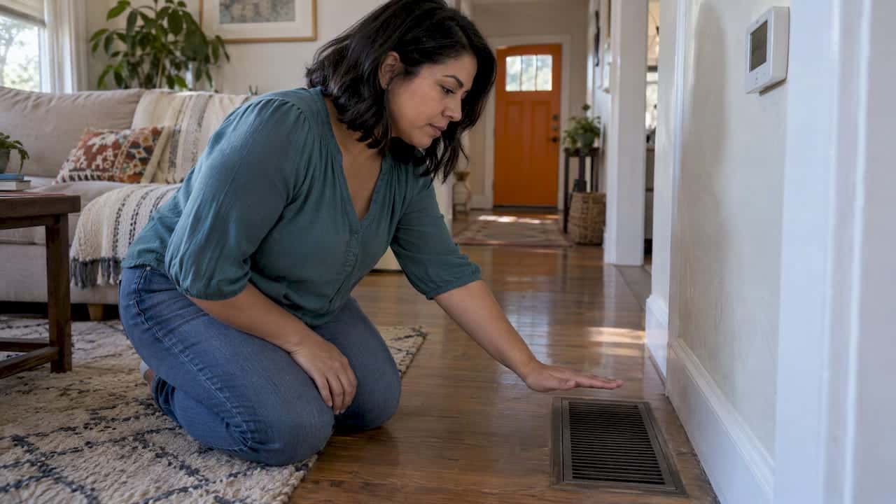
Common signs of a failing control board include no system startup, intermittent operation, fans running without cooling, thermostat non-response, and a burning electronics smell. Here are the five most diagnostically useful symptoms, in order of how quickly they point you toward the board.
-
No response to thermostat with 24 VAC present. You’ve confirmed voltage at R and C, but the system does nothing when you call for cooling. This is the clearest indicator of a board-level logic failure. Fastest test: jump R to Y at the air handler and listen for the outdoor unit to start.
-
Intermittent cycling or short-cycling. The system starts, runs briefly, then shuts off without reaching the set temperature. This can mimic a refrigerant or sensor issue, so also check pressure switch continuity before blaming the board.
-
Outdoor unit fails while the indoor fan keeps running (or vice versa). The board controls each output stage separately. When one stage goes dark while others work, a specific relay or output driver on the board has likely failed. Check the contactor and relay before condemning the board.
-
Continuous rapid clicking from the air handler cabinet. A relay on the board that’s stuck in a fast open/close loop produces this sound. It can also come from a failing transformer, so verify 24 VAC first.
-
Burning electronics smell or visible scorch marks. This is the most urgent symptom. Shut power off immediately. A dead LED or no diagnostic lights often means the board isn’t receiving 24 VAC or the low-voltage fuse is open, but scorch marks mean something has already failed catastrophically.
Overlapping causes to rule out first: A failed transformer, a bad thermostat, a tripped pressure switch, or a failed run capacitor can produce every one of these symptoms. Don’t condemn the board until you’ve cleared those inputs.
Safety first: what you need before you start testing
Power off is non-negotiable. Safe homeowner diagnostics start with shutting off the breaker and the disconnect switch at the outdoor unit, then confirming the circuit is dead with a non-contact voltage tester before you open any panel. Never probe live high-voltage terminals.
Safety checklist:
- Turn off the system at the thermostat first, then shut the breaker, then open the disconnect.
- Confirm dead with a non-contact voltage tester at the air handler disconnect and at the outdoor unit.
- Remove service panels carefully and set screws aside where you won’t lose them.
- Photograph all wiring, connector positions, and terminal labels before unplugging anything.
- Keep the area dry; never work near standing water or a wet cabinet.
Tools you’ll need:
- True RMS digital multimeter (Fluke 117 or equivalent)
- Non-contact voltage tester
- Insulated gloves and safety glasses
- Phillips and flathead screwdrivers
- Needle-nose pliers for connector pins
- Phone or camera for documentation
Work within NFPA 70 (the National Electrical Code) boundaries: low-voltage (24 VAC) control wiring is within a careful homeowner’s reach, but the high-voltage supply side of the air handler is not.
Pro Tip: Write down the board’s model and part number before you remove it. Also photograph the serial number label on the unit. You’ll need both to source a compatible OEM replacement, and on communicating or inverter-driven systems, the firmware revision on the board matters too.
How to diagnose an AC control board failure step by step
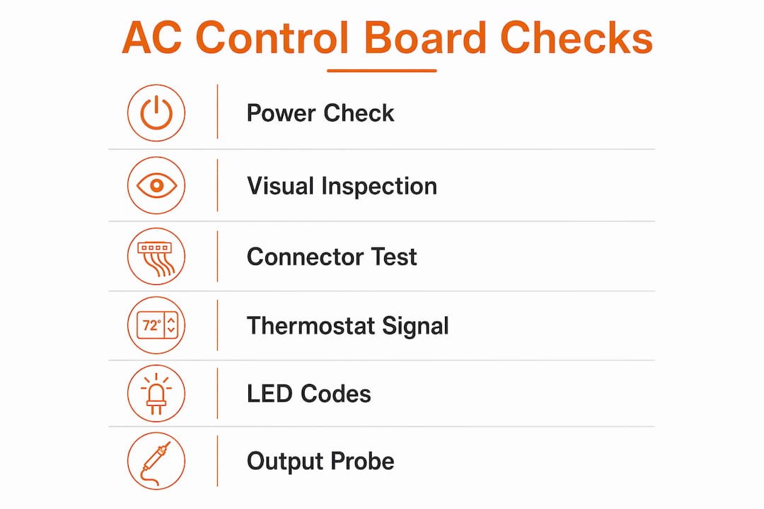
Work through this sequence in order. Each step either confirms the board is at fault or points you to a cheaper, simpler fix upstream.
Step 1: Verify the power chain
- Check the breaker and the disconnect for a tripped or loose connection.
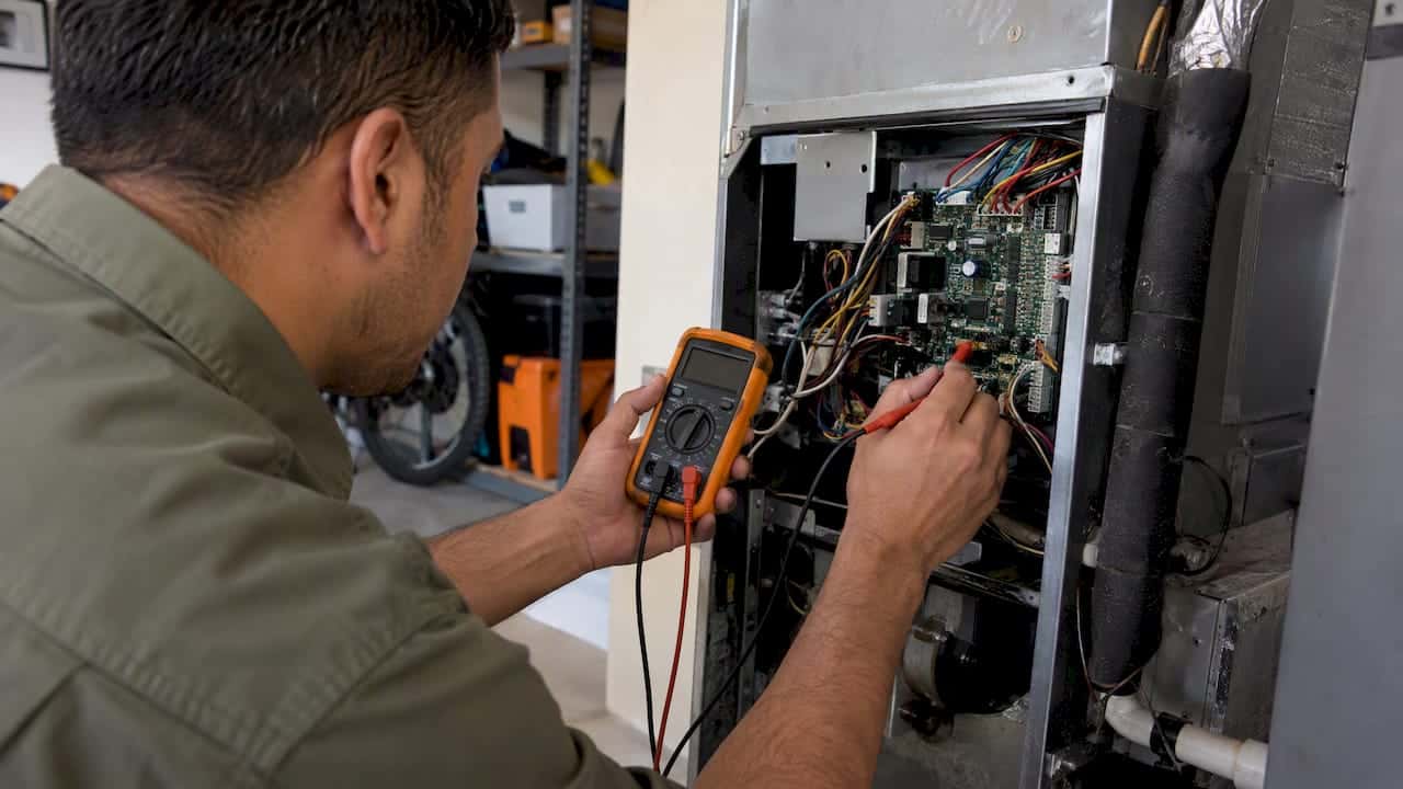
- Set your multimeter to AC voltage and measure the transformer secondary output at the R and C terminals on the board. You should read approximately 24 VAC, with a tolerance allowing for some variation around that level. A reading outside that range points to a failing transformer, not the board.
- Locate the onboard low-voltage fuse (usually 3A or 5A, in a small blade or glass fuse holder on the board). Set your meter to continuity and test it. A blown fuse is a $2 fix, and it often blows because of a downstream short, so find that short before you replace the fuse.
Step 2: Visual inspection
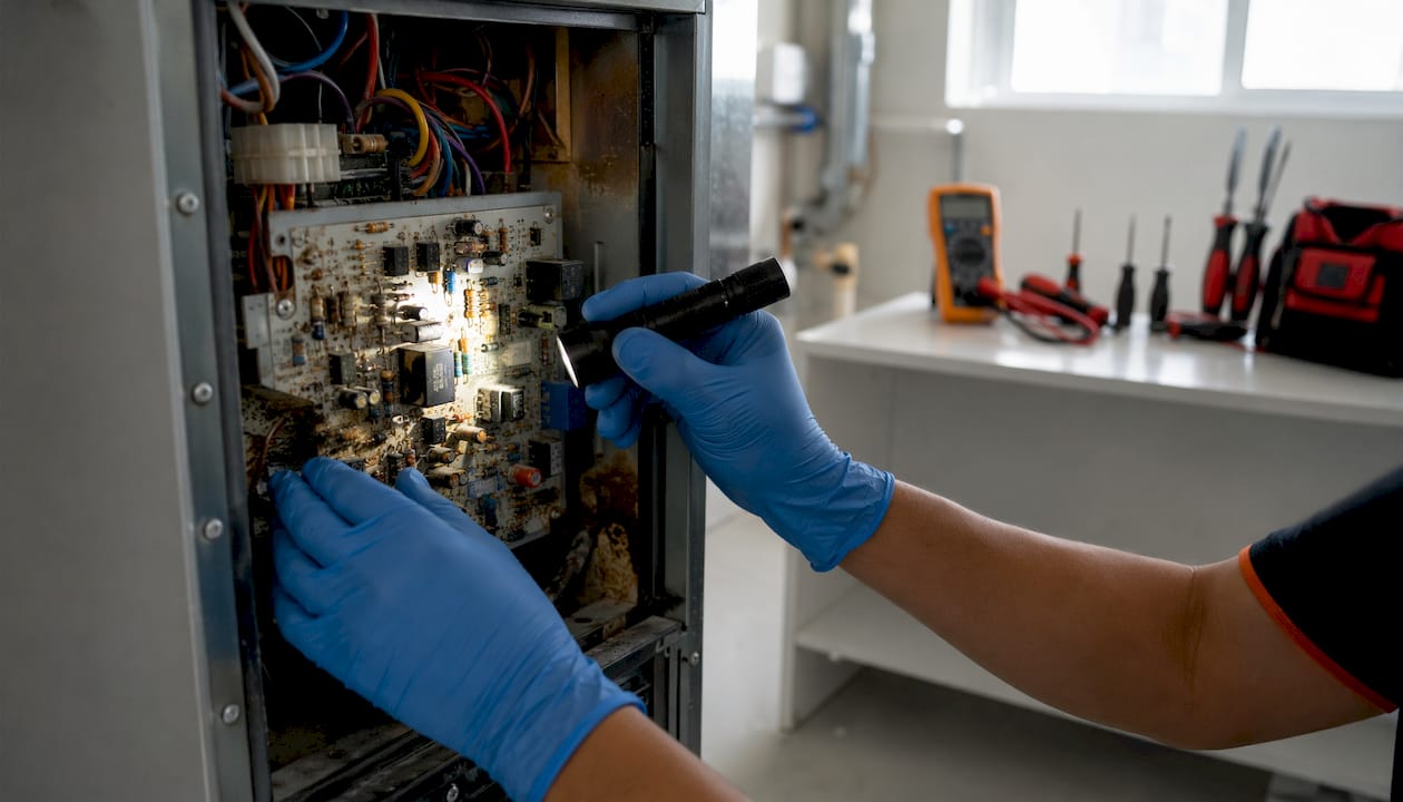
Look for corrosion or moisture staining, burn marks or discoloration, swollen or leaking electrolytic capacitors, cracked solder joints around relay pins, and discolored or melted connector housings. Voltage spikes, moisture, and thermal stress on electrolytic capacitors are the primary causes of board failure, so physical evidence of those conditions is meaningful. Photograph every finding.
Step 3: Connector and harness checks
Reseat every Molex plug and push-on connector firmly. Inspect each connector’s pin for green corrosion or pushed-back pins. Run your fingers along the wiring harness and look for chafed insulation, especially near sheet-metal edges where arcing can occur. A loose connector can produce every symptom on the list above.
Step 4: Thermostat and control signal checks
Disconnect the thermostat wiring at the air handler board and jump R directly to Y (for cooling) using a short piece of wire. If the system starts normally, the board is receiving and responding to a valid call, which means the fault is in the thermostat or its wiring, not the board. If nothing happens, the board is not responding to a valid input signal.
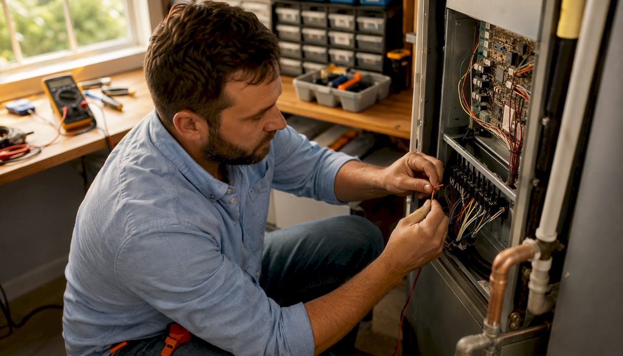
Step 5: Read the LED diagnostic codes
Most modern control boards have one or two status LEDs that flash a pattern when a fault is detected. Count the flashes and compare them to the fault code chart, which is usually printed on the inside of the service panel door or in the equipment manual. A steady green light typically means normal operation; a specific flash sequence points to a particular fault (pressure switch open, limit tripped, ignition lockout, etc.). A dead LED with no diagnostic lights usually means the board isn’t receiving 24 VAC or the low-voltage fuse is open, not that the board’s logic has failed.
Step 6: Probe outputs under a valid call
With power restored and a confirmed cooling call (R jumped to Y), carefully measure the output voltage at the compressor contactor coil terminals and the fan motor terminals. A healthy board should deliver approximately 24 VAC to those outputs during a call. Zero volts at an output terminal while inputs are correct points to a failed relay or output driver on the board.
Field diagnostic standard: Measure transformer secondary voltage over a five-minute period while the system cycles. A transient voltage sag during compressor start that drops more than roughly 10% of nameplate voltage can reset the board’s microprocessor mid-cycle and mimic a board failure. This is a common misdiagnosis.
When to stop and call a technician:
- You find evidence of arcing, burn marks, or melted connectors.
- The board has failed more than once in the same system.
- The system uses a communicating or inverter-driven board that requires firmware.
- Any repair requires working on live high-voltage terminals.
Pro Tip: Always measure under load, not just at rest. A connector that reads 24 VAC with no load can drop to near zero when the compressor tries to start, revealing a high-resistance connection that a static test misses.
| Symptom | Fastest test | Likely cause |
|---|---|---|
| System won’t start, LED off | Measure R to C with multimeter | Failed transformer or blown low-voltage fuse |
| System won’t start, LED active | Jump R to Y at board | Thermostat or wiring fault |
| Outdoor unit off, indoor fan runs | Measure 24 VAC at contactor coil terminals | Failed board relay or bad contactor |
| Continuous rapid clicking | Verify 24 VAC at transformer secondary | Failing transformer or stuck relay |
| Short-cycling | Check pressure switch continuity | Pressure switch, refrigerant issue, or board fault |
| Burning smell or scorch marks | Visual inspection, power off immediately | Arcing, moisture damage, or capacitor failure |
Should you repair or replace the control board?
Some faults are genuinely fixable without touching the board at all. Others require a full board swap. Knowing the difference saves you money.
Commonly repairable without replacing the board:
- Blown onboard fuse: $2–$5 in parts, five minutes of work. Find the cause of the short first.
- Loose or corroded connector: reseat or clean the pin, no parts cost.
- Failed transformer: $20–$60 in parts, straightforward swap for a technician.
- Bad thermostat: $25–$150 depending on model; a thermostat replacement is well within DIY range for most homeowners.
- Failed external sensor or pressure switch: $15–$50 in parts.
Not advisable as DIY repairs:
- Soldering replacement relays onto the board. Field PCB repair is typically temporary; surrounding components are often aged and will fail soon after a patch.
- Bridging cracked traces with conductive epoxy.
- Flashing firmware on communicating or inverter boards.
- Any surface-mount component replacement.
Full board replacement: cost and timeline
A single residential control board replacement typically runs several hundred dollars for parts plus labor, depending on board complexity and your region. Labor on-site usually takes about one to two hours. Costs vary significantly between simpler single-stage boards and more complex communicating or variable-speed boards with higher parts cost.
Repair vs. replace: the honest tradeoff
- Repair upstream components: lower cost now, but if the board itself has sustained damage from the original fault (a voltage spike that blew the fuse also stressed the board’s logic), you may face another failure within a season.
- Replace the board: higher upfront cost, but a professional installation comes with a parts warranty and a labor warranty, and a new board starts fresh.
Surge protection at the disconnect or main panel is the most effective follow-up investment after any board replacement, especially in areas prone to storms or grid surges. For systems more than 12–15 years old, also weigh the cost of a board replacement against the economics of AC repair vs. full system replacement.
How to prevent future control board failures
The good news: most repeat board failures are preventable with a few low-cost habits.
- Install a dedicated HVAC surge protector at the disconnect or main panel after any board replacement. This is the single highest-impact protection you can add. Surge arrestors cut long-term replacement frequency significantly.
- Change filters on schedule. Dirty filters and high ambient humidity increase heat and moisture exposure inside the air handler cabinet, accelerating component degradation. A clogged filter is a small problem that quietly shortens board life.
- Keep the cabinet dry. Check the condensate drain line and drain pan seasonally. Standing water near the board is a direct path to corrosion.
- Inspect wiring harnesses annually. Look for chafing against sheet-metal edges and any sign of insulation wear. Catching a harness fault early costs nothing; ignoring it can take out a new board.
- Avoid frequent manual on/off cycling. Every compressor start puts a transient load on the control circuit. Let the thermostat manage cycling, rather than toggling the breaker.
- Schedule a seasonal inspection. A technician can catch swollen capacitors, loose connectors, and early corrosion before they cause a failure. Good AC return air and clean filters are the simplest things you control between visits.
Pro Tip: If your board failed after a storm or a power outage, surge protection is not optional on the replacement. The same grid event that killed the first board will kill the next one without it.
When should you stop DIY and call a licensed technician?
Some situations are clear stop signs. If you see any of the following, put the panels back on and make the call.
Red flags that require a licensed technician:
- Visible arcing marks, melted connectors, or burn damage anywhere in the cabinet.
- The board has failed more than once in the same system within a short period.
- No 24 VAC at the board with the breaker on and the transformer intact (suggests a wiring fault that needs tracing).
- The system uses a communicating protocol (Carrier Infinity, Trane ComfortLink, Lennox iComfort) or an inverter-driven compressor. Correct firmware and board revision matter on these systems; a close physical match with a different revision can produce hard-to-diagnose behavior.
- Any repair requires reconnecting live high-voltage wiring.
Questions to ask your technician before they start:
- Which upstream inputs will you test, and how? (Transformer output, fuse continuity, sensor and pressure switch continuity.)
- Will you photograph and document the wiring before disconnecting anything?
- What is the part warranty on the replacement board, and what is your labor warranty?
- Do you recommend surge protection after the replacement, and can you install it at the same visit?
What a credible diagnosis report should include:
- Written findings listing which upstream inputs were tested and ruled out.
- OEM part numbers for any recommended replacements.
- A clear cost breakdown separating parts from labor.
- Recommended next steps if additional faults are found.
Homeowners frequently pay for unnecessary board replacements because technicians skip a complete upstream check. Asking for documented testing before authorizing a replacement is the single most effective way to avoid that outcome. LC Heating and Air Conditioning provides written diagnostic findings as a standard part of every service visit, so you always know exactly what was tested and why.
Pro Tip: Ask the technician to show you the multimeter readings for transformer output and fuse continuity before they quote a board replacement. A tech who can’t or won’t show you those readings hasn’t completed the diagnostic.
Your immediate action plan for right now
If your AC isn’t working and you suspect a control board issue, here’s the short version of what to do.
- Step 1: Shut off power at the breaker and the disconnect. Confirm dead with a non-contact tester.
- Step 2: Photograph all wiring and connector positions on the board.
- Step 3: Check the onboard fuse with a multimeter. If it’s blown, find the cause before replacing it.
- Step 4: Measure transformer secondary output at R and C. You need ~24 VAC ±10%.
- Step 5: Jump R to Y to bypass the thermostat. If the system starts, the board is fine.
- Step 6: Read the LED fault codes and look them up in your equipment manual.
- Step 7: If inputs are all correct but outputs are dead, the board is likely the fault. Stop here and call a technician.
For Los Angeles homeowners who’d rather skip the testing and get a same-day answer, LC Heating and Air Conditioning offers same-day AC diagnostics with flat-rate pricing and no surprise fees.
Pro Tip: If you’re not comfortable with a multimeter or you’re unsure what you’re measuring, stop at Step 2. Photographing the wiring is still useful for the technician and costs you nothing.
Key Takeaways
Ruling out upstream inputs before replacing the control board is the single most important step, because up to 30–40% of suspected board failures are actually caused by a failed transformer, blown fuse, or faulty sensor.
| Point | Details |
|---|---|
| Verify power first | Confirm ~24 VAC at R and C before any other test; a dead board may just have a blown fuse. |
| Rule out upstream inputs | Up to 30–40% of board failures are actually caused by faults in the transformer, fuse, or sensors rather than the board itself. |
| Avoid solder-level DIY repairs | Field PCB repairs are typically temporary; full board replacement is the durable fix. |
| Add surge protection after replacement | A dedicated HVAC surge protector at the disconnect is the most cost-effective way to prevent repeat failures. |
| LC Heating and Air Conditioning | Provides same-day diagnostics with documented test results and flat-rate pricing for Los Angeles homeowners. |
What most guides get wrong about control board diagnosis
Most articles on this topic treat the control board as the default suspect the moment an AC system stops responding. That framing costs homeowners real money. The board is actually one of the more durable components in a modern air handler; it’s the electrical environment around it, specifically voltage spikes, moisture, and thermal stress from clogged filters, that causes most failures.
The more useful mental model is to think of the board as the last thing you confirm, not the first. Work outward from the power supply: transformer, fuse, connectors, thermostat signal, external sensors. If every input is correct and the outputs are still dead, then you’ve actually earned the diagnosis of a failed board. That’s a very different process from what a lot of homeowners experience, where a technician spends ten minutes in the cabinet and quotes a board replacement without showing a single meter reading.
There’s also a subtler issue with communicating and inverter-driven systems that almost no homeowner-facing guide addresses: the firmware revision on the replacement board matters. A board that looks identical and has the same base part number but carries a different firmware revision can change timing parameters and sensor thresholds in ways that produce intermittent faults for months before anyone connects them to the replacement. Always confirm the full OEM part number and revision before ordering.
The practical takeaway is straightforward. Do the upstream checks yourself if you’re comfortable with a multimeter. If you’re not, at minimum ask your technician to walk you through what they tested before they quote a replacement. A good technician welcomes that question.
LC Heating and Air Conditioning: same-day diagnosis, no guesswork fees
When the DIY checks point to a board failure, or when you’d simply rather have a professional handle it from the start, LC Heating and Air Conditioning brings same-day diagnostics to Los Angeles homeowners with flat-rate pricing and no surprise charges. Every service visit includes a documented test report showing which upstream inputs were verified, so you know exactly what was tested and why a replacement is recommended before you authorize any work.
Board replacements come with a parts and labor warranty. Surge protection installation is available at the same visit, which is the most practical way to protect a new board from the grid events that likely caused the original failure. Whether you need a straightforward fuse swap, a full board replacement, or a second opinion on a diagnosis you’re not sure about, the team at LC Heating and Air Conditioning handles it transparently.
Call (323) 970-3113 or book a same-day appointment online. For a full overview of AC repair and maintenance services, visit the HVAC services page.
Useful sources and next reading
The resources below are useful for deeper technical detail or to book service. For any work involving live high-voltage wiring, consult a licensed HVAC technician.
- How to diagnose AC not cooling: a homeowner’s guide — LC Heating and Air Conditioning
- What to do when your HVAC system won’t turn on — LC Heating and Air Conditioning
- HVAC troubleshooting and how-to guides — LC Heating and Air Conditioning
- How central AC works: a homeowner’s guide — LC Heating and Air Conditioning
- HVACR control board diagnosis — GSIstore technical guide
- HVAC control board failure: diagnosis and replacement — HVAC Repair Authority
- AC control board failure: symptoms and replacement guide — DABUND
These sources are for further reading and self-diagnosis only. Always consult a licensed technician before working on live high-voltage components.
FAQ
How much does it cost to replace an AC control board?
A residential control board replacement typically costs $350–$900 for parts plus labor, with on-site labor usually running 60–120 minutes. The range reflects the difference between a basic single-stage board and a communicating or variable-speed board, which carries a higher parts cost.
How can you tell if an AC control board is bad?
The clearest sign is no system response to a valid thermostat call when 24 VAC is confirmed at the board. Common indicators also include intermittent cycling, one system stage running while another doesn’t, continuous relay clicking, and a burning electronics smell.
Can a control board be repaired rather than replaced?
Minor upstream faults like a blown fuse, a loose connector, or a failed transformer can be repaired without touching the board. Solder-level repairs to the board itself, such as replacing relays or bridging traces, are typically temporary fixes because surrounding components are usually aged and will fail soon after.
How long should an AC control board last?
Control boards don’t fail on a predictable calendar schedule. Failures are driven primarily by the electrical environment: voltage spikes, moisture, and thermal stress from dirty filters or high humidity accelerate degradation far more than age alone. A board in a well-maintained system with surge protection can last the life of the equipment; one exposed to repeated grid surges may fail within a few years.
What should I ask a technician before authorizing a board replacement?
Ask which upstream inputs were tested (transformer output, fuse continuity, sensor and pressure switch continuity) and request written documentation of those readings. Homeowners frequently pay for unnecessary replacements when technicians skip a complete upstream check. LC Heating and Air Conditioning provides documented test results as standard practice before recommending any board replacement.
Recommended
Leo, Owner & Lead Technician at LC Heating & Air
Leo leads LC Heating & Air as an owner-operator and holds California CSLB C-20 HVAC license #1073586. His guides focus on practical diagnostics, safe repair decisions, and clear advice for Los Angeles homeowners.